Link to Don’s article that was originally published at Motoiq
BMW 2002-cylinder heads are not the worst cylinder heads ever made to try and improve but they are definitely in the running. The 2002 port runners are short and the short sides go right up to the back of the valve seat inserts and there is little to no short side radius. You can mess around with the port runners for months and never get them to flow much better. I have tried numerous times in the past with limited success. So, when Raffi, the owner of The Pit Stop, a high-end exotic car garage in Brisbane, Ca. told me to be creative and make it the best 2002-cylinder head ever, I may I confess, have possibly become sexually aroused. A good customer was giving me the rare chance, to do something well beyond the norm and ordinary. Something Great! Something Bigly!! Something Covfefe!!!
Since the gains to be gotten from the 2002 head are finite when it comes to just porting we had to think out of the box. To go beyond porting, we would have to think about thermodynamics and combustion. Internal Combustion engines work on basic Thermodynamic and a few other scientific principles. The prime thermodynamic principals include Volume, Pressure and Temperature. Each of these can refer to a number of states and actions in our engine. Volume can be noted as a measurement reference as to a cylinder’s Swept Volume. IC engines breathe on a “Per Volume” basis. There is also the Volume of the crankcase which also has its effects on operation, but we will pass that by for now. Without Pressure there would be no compression of the in-cylinder Air/Fuel charge, and there would be no external pressure on the Air/Fuel charge to assist it entering into the engine.
Atmospheric or Barometric pressure is how much the weight of the ocean of air that we live under is pressing upon us. This pressure is relative to our elevation in the Troposphere. Barometric pressure also changes with weather conditions. Barometric pressure is higher at sea level than it is on the top of a mountain. Or the higher one goes up into the Troposphere the less are the effects felt by the weight of our ocean of air. Temperature affects the amount of Oxygen in the air that we and our IC engines need to breathe and survive. Cooler temperatures will generally, but not always, provide more oxygen molecules per a given volume of air. Oxygen content is also affected by the amount of water in the air. But again, we do not want to make this story overly complex at this time.So, what does all of this mean? It means that our wonderful Internal Combustion engines are, at an elemental level, thermodynamically driven.
I spent some time thinking about what I had done to 2002 heads in the past and knew that I could just about port this thing with a sand paper roll and make it as good as it was ever going to get. Or I could put the cylinder head on Mister Flow Bench and do some testing and thinking. I began testing both CFM and velocity numbers in the port runners. I wanted to find out if this thing had any secrets. I needed to think positively! Try a new approach to thinking about this problem child and try something new.

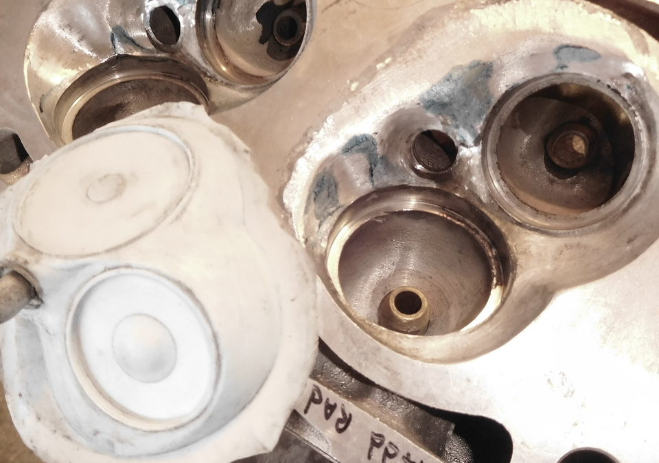
Not every cylinder head’s air flow problems are located in the port runners. For some heads, you can grind in the runners until you start to see shapes in the port runner walls that look just like Jesus on a tortilla. That might get you an audience with the Pope, a room in a padded cell, but it will not likely proffer any helpful relatable airflow information. So, I started looking beyond the port runner and to the combustion chambers. I put some clay in the chamber and put the head back on Mr. Flow Bench. The intake air flow picked up! I did some more sculpting. The cylinder head was now traveling back and forth from my porting/work bench to Mr. Flow Bench. I had started to wear a game trail into the concrete floor. But the intake port runner air flow had continued to pick up. It picked up enough that the clay started peeling off the chamber walls. There was now too much air flow for the clay to adhere. Excellent!!!
I mixed up some epoxy and started filling in the combustion chamber areas where the clay had previously been. The next day after the epoxy had hardened, I started to do some conservative shaping. The flow slowly started to return to the numbers that I had seen in the day before, so I shaped the chamber some more. The head’s air flow kept getting better. I was now wearing a deeper path in the concrete floor between Mr. Flow Bench and my work table.
I continued this routine over the next few days until I had a definitive shape. What I have described here took many, many hours spread out over days of testing and shaping. This is very slow, detailed, and tedious work. It is not a box of Lego’s or a Christmas jigsaw puzzle prize from your favorite Aunt. Airflow Trolls do not suddenly jump up out of Mr. Flow Bench and tell you what you should do. You have to listen; watch the numbers and look for clues. Use your flow tools in the port runners, watch for turbulence and dead spots, etc. You have to think and figure it out with this and other such cases by trial and error. Cylinder heads do not come with improvement instructions with regards to port flow CFM and especially not port velocity.
I wanted the intake flow to spiral around and down the cylinder bore. Not as per stock which had the charge blowing out the intake valve and straight across and out the exhaust port during overlap. I did a little backyard wet flow test to confirm that I was moving in the right direction. I was. After I had tested my modifications backwards and forwards for a few days. I made a silicone mold of the port and then had my friend Robbie, The Welder, weld up the four combustion chambers.
Old aluminum is usually very difficult to weld. Old aluminum cylinder heads have decades of combustion gasses, fuel residue, and the residue of everything that passes through the combustion chamber driven into the metal. When you heat the cylinder head with a TIG torch, all of this junk bubbles up and rises to the metal’s surface and contaminates the weld puddle. Robbie has been TIG welding professionally for some four decades now. He is so good he could weld the crack of an ass. I knew that he could handle this and he did so with flying colors.
We mounted the head on a 5/8-inch-thick Blanchard ground flat steel plate. I had the plate ground flat when I was doing a lot of airflow work for Mazda Speed. We drilled the plate to accept hold-down bolts for this head that coincided with this cylinder head’s head bolts. We ran long bolts through the cylinder head’s head bolt holes and through the plate. We bolted the head to the plate and then carefully torqued down the head to the plate in the standard head gasket torque pattern, center out. The head was heated uniformly and only then did Robbie start welding. Yes, like everything else related to this sort of job, there is a process that you must follow if you expect useful, positive results and a workable product.

With the head back, I started the hard part of shaping the chambers to match the new combustion chamber shape that I had created. There was a lot of aluminum now for me to remove and shape. I had a long way to go to get the welded chambers to match the chamber mold.A digitizer and a 4 or 5 axis CNC Vertical Mill would have been nice at this point. But Santa missed me last Christmas. Though someone did leave me a lump of coal.So, I was going to have to do this the old-fashioned way. All by hand, which is normal, no worries.
As the valve seats were removed when the chambers were welded, it was going to be a while before the new seats would be installed so that I could “CC” the chambers or put the head back on the flow bench to test. I formed the combustion chambers based on the silicone mold that I had made of the epoxy chamber forms. It was invaluable. Photographs are limited and can only reveal so much. I spent a LOT of time carefully forming the chambers. Finally, after a lot of grinding and shaping I was done, for the time being. There is still a good bit of machine shop work to be done with this cylinder head before it is finished and ready to return to the customer. I will do what Chris did and how we did it in Part Two of this Bavarian adventure. Like this part, it will be involved.

There were still additional questions to answer before this project was complete. Were we going to have to weld up the seat pockets to eliminate potential ovality of the seat pockets? Possibly and what about the guide bosses and pockets? We would, of course, machine and re-cut the valve seat pockets to make sure that they actually were round and that all seat pockets were set at a uniform depth.
Years and years of valves pounding against valve seat inserts will distort the valve seat inserts and seat pockets. As I could not visually tell how close the water jacket was to the seat pockets, I wanted to check the thickness of the metal and seat pocket thickness to the water jacket with a sonic depth device. Wonderful tool! Now we knew how deep we could go with this machining part of the operation. That would give us a baseline maximum depth and maximum valve seat pocket diameter so that we would be able to order correct new valve seats.
With the measuring completed, I sent the cylinder head off to my friend Bentzion at CTP to have the head Cryogenically treated. This process stress relieves the cylinder head after the additional stress of welding and age usage. This process also strengthens the head at a very basic molecular level. It makes the parts stronger without making the metal brittle. The parts wear better and last longer. It is a good and worthwhile process with which to treat metal components. I have been using Cryogenics on engines parts for some twenty years now. When done correctly by a competent shop like CTP, the process returns truly marvelous results. It works!
The 2002 BMW Flow Test Numbers. All readings are in Cubic Feet Per Minute (CFM) and were recorded on The Fabulous RMI Flow Bench @ 28 inches of water depression.
Intake Port Exhaust Port
Lift Stock RMI Stock RMI
.050 0.0 31.8 36.6 58.2 14.2
.100 34.8 73.5 72.7 58.2 55.2
.150 75.5 101.3 98.3 58.2 88.4
.200 97.5 126.2 130.4 58.2 112.8
.250 128.7 147.6 156.4 88.8 137.4
.300 151.4 164.4 174.9 109.0 154.5
.350 169.4 175.9 187.4 125.5 166.7
.400 181.2 183.7 191.2 137.8 174.8
.450 185.8 187.3 196.2 142.6 177.2
.500 188.6 192.9 202.4 150.3 182.6
.550 190.2 193.3 205.4 155.1 185.2
.600 193.4 196.1 208.1 158.6 191.2
The above numbers are a sampling of the twenty something plus flow bench tests that I ran on this cylinder head. Stock means exactly that. I tested the cylinder head in an “as I received it condition”. There were no changes or adjustments to any part of the cylinder head for Intake or Exhaust ports. The two different numbers on the left under “Stock” are from the same 2002 BMW cylinder head but taken from two different intake ports and cylinders. Interesting no?
It is quite a long way into the actual valve lift before the CFM numbers start to equal each other. Is this unique to this particular cylinder head? No. Do you ever wonder why your engine will run differently from one day to the next? Or why your engine does not measure up to another of the same type and year? Study the two left CFM columns under “Stock”. This is much more “The Norm” than we would like to realize or that manufacturers would like you to be aware of.

Speaking of weirdness. What I have listed as the “Stock” low lift exhaust port flow numbers are correct. The air flow stalled at 58.2 CFM in that port until 0.250” lift. Like Penny Lane, it was very strange.Under actual engine running conditions the exhaust port and charge is experiencing its highest pressure at these lifts. The exhaust charge will of course evacuate. But the stall in the port runner does not help low lift flow and will contribute to additional engine Pumping Losses. This is a negative to engine overall power output. Not a good thing. Re-read the preceding paragraph. As Bill Shakespeare once noted; “There are more things in heaven and earth, Horatio than are dreamt of in your philosophy.” Philosophy in this case refers to Science and Learning.

I recontoured the combustion chamber to improve the intake air flow and get the four different runners to equal each other in CFM. For the exhaust I installed a “shark fin” on the floor of the exhaust port runner. You can see the improved results.If you want to learn more about Internal Combustion Engine air flow, there are many paths to Air Flow study and learning. My personal path of study includes some Fifty plus years of watching, listening and reading anything and everything I could get my hands on – automotive, motorcycle and aerospace. I have purchased and read countless books, SAE Papers, Journals, magazines, and spent countless hours in college libraries – anything and everything that I felt might increase my base of knowledge. Internal Combustion Engine Airflow is a massive subject that includes amongst other studies, Fluid Dynamics, Thermal Dynamics, Physics, Chaos Theory, Mechanical Engineering, etc., etc., etc. Thinking that you can master this subject quickly, like in a few weeks, which I actually had someone say to my face, is plainly ignorant and self-delusional.
As Frank Zappa (an others) have said. “Ignorance is the most abundant element in the Universe…”
Sources
Chris’ Precision Machine
123 Lee Road Unit F
Watsonville, Ca.
1-831-761-3344
On Face Book @Chris’s Precision Machine
On Instagram@ Chrisprecisionmachine
CTP Cryogenics
2909 Oregon Court Unit C2
Torrance, Ca. 90503
818-445-3030
moc.scinegoyrcptc@noiztneb
Elgin Camshafts
1808 Empire Industrial Court Suite D
Santa Rosa, Ca. 95403
707-545-6115
Harold is a private consultant on engine matters
His book “Engine Airflow” is a must read for anyone wanting to know more on this subject
https://hotrodenginetech.com/engine-airflow/
https://www.summitracing.com/parts/hpb-hp1537
https://www.amazon.com/Engine-Airflow-HP1537-Practical-Performance/dp/1557885370
Replika Maschinen, Inc
Watsonville, Ca. 95076
831-359-0863
-By appointment only-
On Instagram@Replikad
https://www.replikamaschinen.com/
The Pit Stop Automotive
340 Industrial Way
Brisbane, Ca. 94005
415-859-5373
On Instagram@ thepitstopautomotive